Motion systems are customised multi-axis motion platforms offering motion in X, Y, Z, theta, and tip/tilt. The system’s axes are integrated into the driving mechanisms and encoders and offer the “next level” in performance regarding accuracy and speed. Motion systems are delivered as plug-and-play with all electronics integrated.
Motion systems can offer both, long and short travel, or a combination. Drive mechanisms are typically linear motors for the long travel axes and ball screws, and piezo motors or voice coils for the short travel axes.
For linear guides, a combination is used for long travel, with recirculating guides or air-bearings. The shorter axes are typically designed with cross-roller guides for repeatable accuracy and smooth motion. The most common axes are X-and Y-axis, Z-axis, Theta-axis and Gonio-axis.

Positioning stages or positioning systems include two or more axes providing precision motion in X, Y, Z, rotary or tip/tilt. The stages are built with linear tables, include the drive mechanisms, and are mounted on each other. In some designs the X and Y-axis are integrated, offering a monolithic design.
A monolithic design means that the top of the bottom axis and the base of the top axis are integrated into one piece. These stages are primarily used for high-precision applications. The linear bearing of choice is a type of crossed-roller or needle roller guide, as these provide extremely smooth and precise travel with high load ratings and rigidity.
Linear stages are constructed with a precision machined steel or aluminum top and base. They use high-precision linear guides such as cross roller guides and use different driving mechanisms (ball screw, linear motor, or piezo motor). For positioning feedback, they can be equipped with linear encoders. Linear tables offer single-axis straight-line motion with low friction and high precision.
In addition to linear slides, there are also miniature linear slides or miniature linear tables. They are preloaded differently than the previously mentioned slides with cross-roller linear guides. In the case of miniature linear slides, the linear guides are integrated into the table parts. By geometric pairing, the preload can be determined by the choice of roller diameter size.
Miniature linear slides are available in three versions:
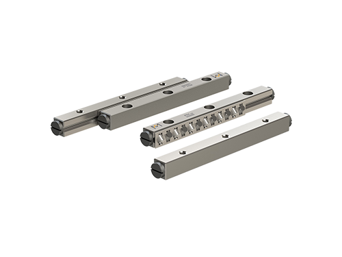
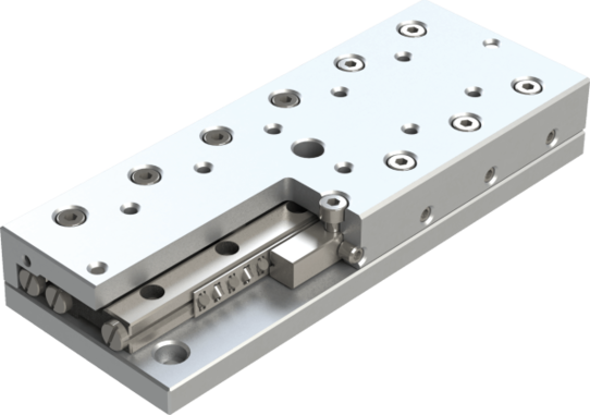
Linear slides are also called precision linear tables or crossed roller linear tables. They are constructed with precision-machined top and base plates made from aluminum, (stainless) steel or cast iron. The top and base have equal lengths. These table elements are equipped with precision cross-roller linear guides to enable straight-line precision motion with low friction. These linear bearings are factory preloaded to eliminate play. The linear slides are available in standard sizes and lengths and also as miniature slides. All slides have a standard pattern of attachment holes for mounting in your application.
People and companies worldwide use these words interchangeably. However, there are differences between the products. That’s why below, we explain these differences using generally accepted terminology.
Yes, this is possible. However, at temperatures above 150 °C, the hardness of the guideways and rolling elements will degrade, which will reduce the load-carry capacity and the linear guide lifespan. Also, modifications to the cages and the lubrication will be necessary. In case of high, or low temperatures, ceramic linear bearings could be an option. Click here for more information on ceramic linear bearings.
PM slides are capable of operating in a temperature range of -30 to +120 °Celcius (C). For slides which contain plastic cages, the operating temperature range is -30 to +80 °C. For special applications, such as cryogenic or high-temperature applications, please contact support with your specific question.
No, PM linear slides are factory-lubricated and ready-to-use at delivery. For maintenance, we recommended adding a small quantity of lubrication at least twice a year or to lubricate whenever the linear guides appear to be running in dry condition.
ACCI stands for Anti-Cage Creep Integrated. This is an equally robust and well-proven solution for stainless steel precision linear bearings. ACCI differs from ACC in that a gear rack is embedded in the bottom of the rails’ V-groove. Also, a pinion is located in the centre of the cage.
Anti-cage creep solutions are popular in precision linear bearings, as they keep the cage in position during high acceleration, deacceleration, and vertical mounting orientations. It is a reliable solution for use in vacuum and ultra-high vacuum applications. ACCI is available in stainless steel crossed roller linear bearings type RSDE-SS and type RNG-SS.
The running resistance, or friction force, required to move the linear bearings is influenced by several factors including the quality of the linear guides, the preload height, and the moving mass. PM linear guides are renowned for their exceptional quality, precision, and running performance. The rails, roller bodies, and cages utilized meet the most stringent requirements.
During the initial movement, the friction force will be slightly higher compared to continuous movement, as more force is necessary to initiate motion than to sustain it.
To determine the running resistance, it is appropriate to assume a coefficient of friction ranging from 0.0005 to 0.004.
For linear guides equipped with wipers, the values of running resistance are notably higher due to the contact between the wipers and the running surfaces.
The calculation for running resistance is as follows:
Fr = µ x F
Where:
Fr = running resistance (N)
µ = coefficient of friction
F = load on the linear guide (N)
ACC stands for Anti-Cage Creep. This is a robust and well-proven solution, which uses a gear rack mounted in the bottom of the guideways’ V-groove and a pinion in the cage’s centre. It is used in precision linear bearings, and keeps the cage in position during high acceleration, deacceleration and vertical mounting orientations. ACC is available in crossed roller linear bearing types RSDE and RNG.
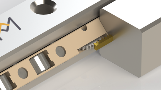
Cage creep is a phenomenon where a cage shifts from its original position in a linear bearing. The result of cage creep is a reduction in the available travel, an increase of friction and shorter lifespan due to premature wear. It can occur in the following situations:
PM offers a solution with anti-cage creep technology. This solution is integrated into the linear guide design and is called ACC (Anti-Cage Creep). For certain stainless steel linear bearings, there is an ACCI (Anti-Cage Creep Integrated), in which the rack is machined in the guideways.
Follow this link to learn more about the solution we offer to eliminate cage creep.
The 3D CAD models can be found on this page: https://www.pm.nl/resources/cad

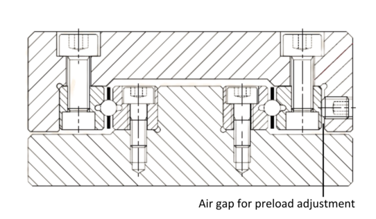
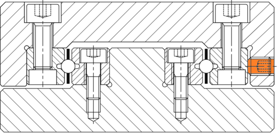
The most common method for applying preload to the precision linear guides is the use of lateral set screws.
The amount of preload depends on the rolling element type (ball, cylindrical roller, needle roller), rolling element size, and guideway type.
In our catalogue, you can find information on the type and amount of set screws to use, as well as the recommended torque to be applied.
In this online article, a step-by-step assembly manual for precision linear guides is given.
For other, non-standard applications or special requirements, please contact us.
The width dimension for a linear guide pair is manufactured with a +0/-0.xx tolerance. This means that a narrow air gap of 0.1 mm is sufficient for setting the preload.
Yes, for a play-free, uniform, smooth, and precise motion, preloading of linear bearings is necessary. An incorrect preload can cause play, excessive friction, and even wear, so make sure to use an adequate preload (see next section).
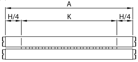
The stroke is calculated with the guideway length and cage length.
The following equation applies:
Stroke: H = (A – K) x 2
H = Stroke (in mm)
A = Guideway length (in mm)
K = Cage length (in mm)
For optimal stiffness and straightness/flatness, PM recommends applying stroke lengths of up to 70% of the guideway length.
PM anti-friction guideways are available in various models with ball and roller diameters in many standard lengths and sizes. Their range covers virtually all industrial applications, and allows designers to solve most problems in precision linear movements. PM linear guides are practically free of wear and require little lubrication or maintenance.
A linear guide set consists of:
Linear guide sets with Anti-Cage Creep (ACC) solutions do not have end screws (unless requested). In other words, one set consists of: